Connecting Microchip’s AC164164 PIC-IoT to Medium One IoT Cloud
By Greg Toth for Mouser Electronics
The Microchip® PIC-IoT WG is an Internet of Things (IoT) development board featuring a
PIC® microcontroller, a hardware secure element device, Wi-Fi connectivity, onboard sensors, and
a mikroBUS™ connector for adding a variety of expansion boards. The Medium One IoT Prototyping
Sandbox is a cloud based IoT platform designed to help early stage developers prototype IoT projects or connect
existing hardware to the cloud. In this project, we’ll set up an IoT development environment using the
PIC-IoT WG to read temperature and light sensors and send the data to the Medium One cloud using MQTT. Once the
data is in Medium One it can be processed and viewed using programmable workflows and configurable widget
dashboards.
Project Materials and Resources
The project BOM lists components used in this project. Additional hardware and software development tools are
also identified.
Project BOM
Hardware
- 11 b/g/n Wi-Fi access point with a DHCP server, Internet connectivity, and without a firewall or proxy that
blocks outgoing traffic to the Internet
- Personal computer (PC) running Windows®
Accounts and Software
- Web browser for accessing software download sites and Medium One IoT Prototyping Sandbox
- Login account for the Medium One IoT Prototyping Sandbox
- Microchip MPLAB® X
Integrated Development Environment (IDE)
- Microchip XC16 Compiler
- Microchip MPLAB® Code
Configurator (MCC)
- Application project files available in a GitHub repository found here
- Serial terminal program such as Tera Term on the PC
- Wi-Fi access point connection details including SSID and password
Project Technology Overview
Microchip PIC-IoT WG Development Board
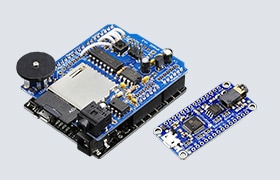
The PIC-IoT WG (Figure 1) is an IoT development board based on the PIC24 family of extreme
low-power microcontrollers. If offers built-in Wi-Fi connectivity for creating IoT applications that communicate
wirelessly with other systems and devices. The Wi-Fi module offloads networking tasks from the main CPU to
maximize processor resources available for your applications. The board can be powered through USB or a
rechargeable battery using the built-in battery charging circuit. The combination of board, microcontroller and
onboard components offer developers a number of features for prototyping IoT designs:
- PIC24FJ128GA705 microcontroller with 128KB of flash and 16KB of SRAM
- Wi-Fi wireless module supporting 802.11 b/g/n
- ATECC608A CryptoAuthentication™ device
- Digital temperature sensor
- Ambient light sensor
- Multiple digital and analog input/outputs
- Serial UART
- I2C and SPI buses
- Lithium polymer (LiPo) battery charger
- Two pushbuttons and four LED indicators
- Onboard device programmer/debugger
- mikroBUS™ expansion connector
Technical documentation for the PIC-IoT can be found here and here.
Figure 1: PIC-IoT WG Development Board (Source: Mouser Electronics)
The board is supported by the MPLAB X® Integrated Development Environment (IDE) and connects to a
PC using a USB cable that supports programming and debugging from the IDE as well as microcontroller serial port
connectivity.
The mikroBUS expansion connector allows you to expand the board capabilities with 450+ sensors and actuators
offered by MikroElektronika through their growing
portfolio of Click boards™.
Microchip MPLAB X® Integrated Development Environment (IDE)
Firmware programs that run on microcontrollers are typically developed and tested using an integrated development
environment (IDE) running on a personal computer. The IDE provides an editor, compiler, linker, debugger, and a
mechanism for transferring binary program images to the microcontroller.
The PIC-IoT WG can be programmed using the Microchip MPLAB X IDE, a NetBeans-based IDE that runs on Windows, Mac
and Linux computers. It connects to the PIC-IoT WG using a USB cable that supports programming and debugging.
MPLAB X can be downloaded for free from the Microchip MPLAB X site.
Microchip XC16 Compiler
Application source code is converted into machine code for the PIC24 microcontroller by the Microchip XC16
compiler which integrates into the MPLAB X IDE environment.
Microchip MPLAB® Code Configurator (MCC)
MPLAB Code Configurator is a free, graphical programming environment that generates seamless, easy-to-understand
C code to be inserted into your project. It integrates into the MPLAB X IDE environment to accelerate the
generation of production ready code.
Project Application Source Code Files
For this project, MPLAB X was used to create an initial set of project source code files that have been modified
and extended to work with the Medium One IoT Prototyping Sandbox. The resulting files have been put in a GitHub
repository that you can download and use for this project. The project files will be opened in the MPLAB X IDE
where they’ll be compiled and downloaded to the PIC-IoT board. The project files consist of a main
application program and supporting functions for MQTT and I/O processing.
Medium One IoT Prototyping Sandbox
The Medium One IoT Prototyping Sandbox (Figure 2) is designed to help early stage developers
prototype their IoT project or connect their existing hardware to the cloud. It offers an IoT Data Intelligence
platform enabling customers to quickly build IoT applications with less effort. Programmable workflows allow you
to build processing logic without having to create your own complex software stack. Configurable dashboards
allow you to visualize application data and view real-time data in a variety of formats. Medium One’s iOS
and Android apps allow you to build simple mobile app dashboards that can communicate with your devices through
the IoT Prototyping Sandbox.
Figure 2: Medium One IoT Prototyping Sandbox (Source: Mouser
Electronics)
IoT devices can exchange data with Medium One through either a REST API or MQTT. More detailed information about
the Medium One IoT Prototyping Sandbox can be found here and on the Medium One site.
The Setup (Hardware)
While setting up the hardware, be sure to remember that electronic components are static-sensitive so handle
accordingly.
Personal Computer (PC)
Power up the personal computer and allow it to boot up.
Wi-Fi Access Point
Make sure your Wi-Fi access point is running with an active connection to the internet and a DHCP server that
assigns IP addresses. You’ll need to know the access point SSID, security type, and security credentials to be
used later when configuring the board’s Wi-Fi module.
PIC-IoT WG
Unbox the PIC-IoT WG board and set it up as described in the PIC-IoT WG User Guide, found here. The user guide describes connecting the board to Google Cloud, however for this
project we’ll be connecting to the Medium One cloud instead.
Connect the PIC-IoT board to the PC using the USB cable. LEDs on the board should light up based on the example
application that comes pre-programmed on the board.
The Setup (Software)
Download and Install MPLAB X, XC16 Compiler and MPLAB Code Configurator
Web browse to the Microchip MPLAB X
site and locate the MPLAB X installer for your type of PC. Run the installer and make sure the following
applications are selected for installation:
- MPLAB X IDE
- Device support for 16-bit MCUs
The other items are not needed for this project and can be omitted to save disk space.
At the end of the installation, two web pages will open automatically. One takes you to a page for downloading
the MPLAB XC16 Compiler. Download the XC16 installer for your operating system and run it to install the
compiler on your machine. You can select the free MPLAB XC16 C Compiler by clicking Next in the
Licensing Information dialog.
The second web page is for MPLAB Code Configurator. You can either download and install it now from the web page,
or you can install it after launching MPLAB X (next step) and install from the Tools > Plugins > Available
Plugins menu item.
Plug the PIC-IoT board into your PC using the USB cable, then launch MPLAB X. If you didn’t already install
MPLAB Code Configurator from the web page, install it now from Tools > Plugins > Available Plugins >
MPLAB Code Configurator > Install and let MPLAB X restart. You can verify whether MPLAB Code Configurator is
installed by navigating to Tools > Plugins > Installed and looking for MPLAB Code Configurator in the list
of installed plugins.
When MPLAB X launches with the PIC-IoT board connected and MPLAB Code Configurator installed, you should see a
main screen with a Kit Window tab that looks like (Figure 3). If it doesn’t look like
this, go back through the PIC-IoT user guide and MPLAB X installation documents to make sure all steps were
followed. Also make sure your PIC-IoT board is connected when you start MPLAB X.
Figure 3: MPLAB X IDE With PIC-IoT Board Detected (Source: Mouser
Electronics)
Download and Open the Project Application Source Code Files
Web browse to the GitHub repository
and find the PICIoT_ MediumOne_1.0.0.zip file. Download that file to your computer and unzip it to create a
directory named PICIoT_MediumOne.X. Move that entire directory and place it in the MPLABXProjects folder on your
PC.
In MPLAB X, select File > Open Project… then select
PICIoT_MediumOne.X from the list and click Open Project. Afterwards the
Projects tab should look like (Figure 4).
Figure 4: After Opening the PICIOT_MediumOne Project in MPLAB X (Source:
Mouser Electronics)
We'll come back to the source code files later after setting up Medium One.
Set Up the Medium One IoT Prototyping Sandbox
Web browse to the Medium One IoT Prototyping
Sandbox and log in. Then, you should see an initial dashboard resembling Figure 2.
Click Setup > Manage Users > Add New User. Set
Username to mydevice, create a password of your choosing and enter it in both
password fields, then click Save. In the Manage API Users list you should see a new user
account having Login ID = mydevice and an auto-generated user MQTT ID like (Figure
5).
Figure 5: Newly Created User ID With Auto-Generated MQTT ID (Source: Mouser
Electronics)
Click Setup > MQTT and you should see a Project MQTT ID and a set
of port numbers like (Figure 6).
Figure 6: Project MQTT ID (Source: Mouser Electronics)
Medium One uses MQTT usernames and passwords for authentication. The MQTT username is created by combining the
Project MQTT ID, a forward slash, and the user MQTT ID. For example, if the Project MQTT ID is
“ZHxxxxxxx0Y” and the user MQTT ID is “sTxxxxxxx8w” the corresponding MQTT username
would be “ZHxxxxxxx0Y/sTxxxxxxx8w”.
Next, we’ll create the MQTT password. Navigate to Setup > Manage API
Keys > Add New API Key. Set the description to mydevice, make
sure Enabled is check-marked, and click Save. The result should look like
(Figure 7).
Figure 7: Newly Created API Key (Source: Mouser Electronics)
The MQTT password is created by combining the API Key, a forward slash, and the mydevice user password.
For example, if the API Key is “PZxxxxxxxxxxxxxxxxxxxxxxxxxxxxxxxxxxxxxxxxxxxMBQ” and the mydevice
user password is “AaaaBbbb3” the corresponding MQTT password would be
“PZxxxxxxxxxxxxxxxxxxxxxxxxxxxxxxxxxxxxxxxxxxxMBQ/AaaaBbbb3”.
The MQTT topic has the following format: “0/Project MQTT ID/User MQTT ID/Device ID”.
The Device ID field can be anything and we’ll use the PIC-IoT’s ATECC608A unique ID (18 hex digits
obtained at runtime) as the Device ID. For example, if the Project MQTT ID is “ZHxxxxxxx0Y” and the
user MQTT ID is “sTxxxxxxx8w” the corresponding MQTT topic would be
“0/ZHxxxxxxx0Y/sTxxxxxxx8w/ NNNNNNNNNNNNNNNNNN” where NNN…NNN is the ATEC608A unique ID
obtained at runtime.
The MQTT username, MQTT password and MQTT topic strings will get added to the project source code in the next
step.
Update Application Source Code Files for Medium One Account Parameters
Set Wi-Fi Connection Parameters
In MPLAB X open project file Header Files/MCC Generated Files/config/conf_winc.h in the editor.
Find these constants and set them to your own Wi-Fi SSID and password info:
- CFG_MAIN_WLAN_SSID
- CFG_MAIN_WLAN_AUTH
- CFG_MAIN_WLAN_PSK
Set Medium One Connection Parameters
Open project file Header Files/MCC Generated Files/config/IoT_Sensor_Node_config.h in the
editor. Find these constants and set them to your own Medium One MQTT parameter strings as described earlier:
- CFG_MQTT_USERNAME
- CFG_MQTT_PASSWORD
- CFG_MQTT_TOPIC – everything except the final Device ID field, which will be added at runtime
*** NOTE *** The current version of the PIC-IoT code is not able to connect to the Medium One MQTT broker
over TLS and this project uses unencrypted MQTT communications between the PIC-IoT and Medium One MQTT
broker. The MQTT username and password are sent over the Internet in the clear and neither the credentials
nor the sensor data are encrypted.
Save the modified file and then build the project. Verify the code compiles without errors. If you see
compilation errors, check the changes you made to the conf_winc.h and IoT_Sensor_Node_config.h files.
Run the Application
Make sure the PIC-IoT board is connected to the PC through USB. Build the program and then download to the
PIC-IoT board. The program should be downloaded to the board and start running. You can connect a serial
terminal program such as Tera Term to the USB serial comm port if necessary to monitor debug messages from the
PIC-IoT while it’s running. Set the serial parameters to 9600,N,8,1.
How the Application Program Works
This program is derived from the PIC-IoT WG Sensor Node example application with the following changes
and enhancements:
- Connect to the Medium One MQTT broker instead of Google Cloud
- Add MQTT username
- Use the ATECC608A unique ID as the Device ID in the MQTT topic name
- Use unencrypted MQTT connection
- Add iteration count data element
- Set data measurement interval to 5 seconds
- Generate a JSON formatted MQTT payload message and send to Medium One MQTT broker
MQTT Payload Format
MQTT messages are formatted as JSON strings according to the Medium One MQTT payload specification. Here’s an
example message:
{"event_data":{"light":40,"tempc":31.87,"iteration":32}}
Fields:
- light = light sensor value
- tempc = temperature in degrees Celsius
- iteration = application loop counter
Try heating or cooling the temperature sensor and covering the light sensor to see the data values change.
View Data in the Medium One Dashboard
In the Medium One dashboard navigate to Data Viewer > Data Streams and click
raw Events. You should see raw messages (Figure 8) being received from the
PIC-IoT. Click the “+” sign to view message details.
Figure 8: Raw Message Display (Source: Mouser Electronics)
Click Dashboard on the top left, then click Add Widget > Single User
Real Time Events Stream to add an event stream widget to the dashboard.
In the Select user dropdown, select mydevice. You should now see messages
appearing in the Real Time Events Stream widget (Figure 9). Click the save icon in the upper
right corner to save your modified dashboard.
Figure 9: Real Time Events Stream Widget Display (Source: Mouser
Electronics)
Add More Widgets
To display more widgets, we need to enable specific data fields contained in the message payload. Navigate to
Config > Data Streams and click on raw Events. The Schema
Map should be pre-populated with fields detected in the incoming messages, however they are currently disabled.
Check-mark the Active box on raw.iteration, raw.light, and
raw.tempc, then click Save Data Stream. These fields are now available for use
in other dashboard widgets.
Back on the dashboard, click the Single User Last Value Table widget and select the
mydevice user within the widget. Click the widget’s Tag Config icon to
the right of the mydevice user selection and check-mark raw:iteration,
raw:light, and raw:tempc, then click Save. The Last Value
Table should now populate with the most recent received values for each field (Figure 10).
Click the Save icon towards the upper right corner to save the updated dashboard.
Figure 10: Last Value Table Widget Display (Source: Mouser Electronics)
Now let’s add dashboard widgets for the temperature and light sensors and iteration counter. Click
Single User Real Time Gauge and select the mydevice user. Click the
widget’s Tag Config icon and check-mark the raw:iteration,
raw:tempc, and raw:light rows, then click Save. The updated
dashboard should look like (Figure 11). Click the dashboard save icon to save the updated
dashboard. Try heating or cooling the temperature sensor and covering the light sensor to see the gauge values
change.
Figure 11: Real Time Gauge Widgets Added to Dashboard (Source: Mouser
Electronics)
At this point, your PIC-IoT board is running continuously, periodically reading the temperature and light sensors
and transmitting data measurements to the Medium One cloud. Remember to power off the PIC-IoT board when
you’re done, otherwise the board will continue to send messages to Medium One and consume daily message
allotments.
Where to Go Next
This project created an end-to-end sensor-to-cloud application that sends real-time sensor data to the Medium One
IoT Prototyping Sandbox. It can be modified and extended in a number of ways and here are a few examples:
- Dive deeper into the application code and board hardware by reading the PIC-IoT documentation and studying
the source code.
- Add more widgets to the Medium One dashboard, such as a real-time line chart of temperature and light
readings.
- Learn about the Medium One Workflow Studio, which lets you create data processing workflows to transform
your sensor data.
- Experiment with the Medium One mobile apps.
- Implement bi-directional communications with the Medium One cloud.
- Modify the sensor data publishing interval by modifying the PIC-IoT application source code.
- Connect other types of sensors to the PIC-IoT board and include the data in MQTT messages.
- Enhance the MQTT communications to support MQTT over TLS.
 Greg is an architect, engineer and
consultant with more than 30 years experience in sensors, embedded systems, IoT, telecommunications, enterprise
systems, cloud computing, data analytics, and hardware/software/firmware development. He has a BS in Electrical
Engineering from the Univ. of Notre Dame and a MS in Computer Engineering from the Univ. of Southern California.
Greg is an architect, engineer and
consultant with more than 30 years experience in sensors, embedded systems, IoT, telecommunications, enterprise
systems, cloud computing, data analytics, and hardware/software/firmware development. He has a BS in Electrical
Engineering from the Univ. of Notre Dame and a MS in Computer Engineering from the Univ. of Southern California.