


Analog Devices / Maxim Integrated MAX25601A/B/C/D Boost-Buck Controller
Analog Devices Inc. MAX25601A/MAX25601B/MAX25601C/MAX25601D Synchronous Boost-Buck Controller is a synchronous boost controller followed by a synchronous buck LED controller. The boost controller's 4.5V to 40V input voltage range is ideal for automotive applications and acts as a pre-boost power supply for the second-stage buck LED controller. The synchronous boost is a current-mode controller that can be paralleled with another device to provide higher output power. A SYNC OUT pin provides the clock to drive the other device's RT/SYNC IN pin, enabling two-phase 180-degree out-of-phase operation. The boost converter can be programmed with a switching frequency of 200kHz to 2.2MHz. A spread spectrum is included to reduce EMI. An internal digital soft-start feature enables a smooth power-up of the boost output. Protection features like hiccup mode, overvoltage protection, and thermal shutdown are provided.
The synchronous buck LED controller uses ADI's F3 Architecture, a proprietary average-current-mode control scheme to regulate the inductor current at a constant switching frequency without any control-loop compensation. The inductor current is sensed in the bottom synchronous n-channel MOSFET. The device operates over a wide 4.5V to 65V input range at switching frequencies as high as 1MHz. Both analog and PWM dimming is included. The LED current can be monitored on the IOUTV pin. Both controllers have high- and low-side gate drivers with at least 1A peak source and sink current capability. Adaptive non-overlap control logic in the ADI MAX25601A/MAX25601B/MAX25601C/MAX25601D Synchronous Boost-Buck Controller prevents shoot-through currents during the transition. Both the boost and the buck faults are monitored on the FLT pin.
Features
- Integration minimizes BOM for high-brightness LED driver, saving space and cost
- Wide input-voltage range from 4.5V to 40V
- Wide boost-output range up to 65V
- Programmable switching frequency optimizes component size
- External MOSFETs can be sized for appropriate current
- Synchronous rectification provides high efficiency and fast transient response
- Average Current-Mode control for buck eliminates compensation components
- Wide dimming ratio allows high contrast ratio
- Analog dimming and PWM dimming
- Analog voltage-controlled PWM dimming
- Protection features and wide temperature range increase system reliability
- Short circuit, overvoltage, and thermal protection
- -40°C to +125°C operating temperature range
- Packages
- MAX25601A: 32-pin SWTQFN package
- MAX25601B: 28-pin TSSOP package
Applications
- Commercial, Industrial, and Architectural Lighting
- Automotive Exterior Lighting
- High-Beam/Low-Beam/Signal/Position Lights
- Daytime Running Lights (DRLs)
- Matrix Light
- Pixel Light
- Adaptive Front-Light Assemblies
Development Tools
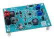
Analog Devices / Maxim Integrated MAX25601EVKIT Controller Evaluation Kit
Evaluates the MAX25601A automotive high-voltage, high-brightness LED (HB LED) boost-buck controller.
Analog Devices / Maxim Integrated MAX25606EVSYS Evaluation System
Demonstration and development platform for the MAX25606 6-Switch Matrix Manager.
Simplified Application Circuit
